It was 12th July 2009 which proved to be the darkest day in the history of DMRC. After achieving a milestone of providing a reliable and easy mean of transportation to the capital of India, it is now facing huge problems which are not only causing loss of human lives but also causing immense damage to the most reputed infrastructure organization of India. So far, this company has achieved every target ahead of schedule under the excellent guidance of Mr. Sreedharan.
Let us try understanding what went wrong on that disastrous day
On 12th July, 2009, while lifting segments of the superstructure, an accident happened in the Badarpur – Secretariat section near P-67. The pier cap of pier P-67 got collapsed causing subsequent collapse of the
(i) Launching Girder
(ii) Span between P-66 and P-67 which had got erected and pre-stressed, already
(iii) Segments of the superstructure for the span between P-67 and P-68.
(i) Launching Girder
(ii) Span between P-66 and P-67 which had got erected and pre-stressed, already
(iii) Segments of the superstructure for the span between P-67 and P-68.
The incident left 6 people dead and many injured.
Site Investigation
After visiting the site, following observations were noticed
1. The pier cap of affected pier (P-67) has sheared from the connection point of the pier and pier
cap. It is a cantilever pier cap. It was informed by the contractor and DMRC representatives that the support system for viaductwas initially designed as portal pier till the casting of the pier was over. The shop owners put up resistance against casting of the other leg of the portal and it was subsequently decided by DMRC that this would be changed to a cantilever pier, similar to P-68 which is still standing at site.
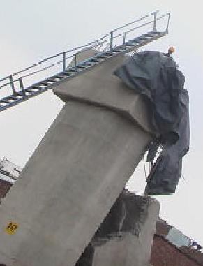
2. It was noticed that the prop support of the cantilever has failed from its connection to the pier.
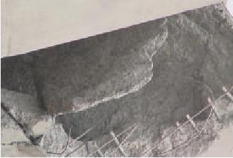
3. The top reinforcement of the cantilever beam does not have any development length into pier
concrete. As learned from the sources, the top reinforcement of the cantilever beam had an “L”
bend of 500 mm only.
concrete. As learned from the sources, the top reinforcement of the cantilever beam had an “L”
bend of 500 mm only.
There is very nominal (or no trace) of shear reinforcement at the juncture.
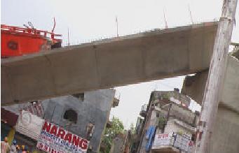
4. The launching girder has fallen below with the failure of pier cap. Also, the span between P-67
and P-68 has fallen inclined, supported by the ground at one end and pier cap (P-68) on the
other.
and P-68 has fallen inclined, supported by the ground at one end and pier cap (P-68) on the
other.
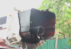
5. The boom of the crane, used for lifting the launching girder on 13 July, 2009, has failed in bending
and shows clear sign of overloading.
and shows clear sign of overloading.
Analysis
i. The pier (P-67) was initially designed as a leg of a portal frame and subsequently changed to support cantilever pier cap.
i. The pier (P-67) was initially designed as a leg of a portal frame and subsequently changed to support cantilever pier cap.
ii. The same method was followed for P-68 and P-66.
iii. The alignment of track here is in curvature and gradually leaves the median of the road to align on one side of the road.
iv. The longitudinal reinforcement of the pier was protruding by around 1500 mm beyond top of pier.
v. The top reinforcement of pier cap was 36 mm in diameter and had a development length of 500 mm. only as an “L” from the top. There was insufficient bond length for the structure to behave like a cantilever beam.
vi. During launching operation of the launching girder itself, this pier cap developed crack and work was stopped for couple of months. During this period, the cantilever pier cap was grouted in crack areas and further strengthened by introducing prop or jacketing.
vii. However, the behavior of the structure changed due to introduction of this jacket and the cantilever pier cap remained no more cantilever.
viii. The segments of superstructure for the span between P-66 and P-67 was erected and launched and the prop beam / jacketing could sustain the load to that extend.
ix. During the launching of superstructure segments between P-67 and P-68, only 6 segments could be lifted and the whole system collapsed when seventh segment was hooked for lifting.
The sequence of failure is as follows:
a. The support of the prop / jacket got sheared from its connection due to inadequate section / welding.
a. The support of the prop / jacket got sheared from its connection due to inadequate section / welding.
b. The cantilever pier cap which was behaving as a simply supported beam due to introduction of prop / jacket started behaving like a cantilever beam suddenly after failure of the prop which it can not sustain ( It was inadequately designed). So, the so called “cantilever pier cap” collapsed.
c. The launching girder / span between P-67 & P-66 / the temporarily erected segments between P-67 and P-68, all got collapsed in one go.
Crane Failure
The launching girder was lifted by the cranes. However, it needed to be pushed little forward for
unloading it on the ground. So, all the cranes were asked to stretch there booms by some length.
During this operation, the 250 MT capacity crane on extreme left exceeded it’s capacity and the
boom failed and broke down. Since, there were unequal loading on the 250 MT crane by it’s side,
that also failed and broke down. The crane of 350 MT capacity didn’t broke but it toppled with it’s
base. The 400 MT crane remained intact.
Final overview
a. It is concluded that the failure of pier cap occurred due to inadequate prop / jacket. This was coupled with failure of cantilever pier cap due to inadequate development length of top reinforcement of the cantilever pier cap.
a. It is concluded that the failure of pier cap occurred due to inadequate prop / jacket. This was coupled with failure of cantilever pier cap due to inadequate development length of top reinforcement of the cantilever pier cap.
b. The failure of the crane was a case of operational inexperience for such synchronized crane operation. The crane -1 did not have the requisite capacity for the extended boom length and radius. Once crane – 1 failed, the crane – 2 was loaded almost half of the launching girder amounting to around 200 MT. For the extension of boom and radius, it did not have the requisite capacity so it failed, too. The crane -3 was loaded more than it’s capacity. However, in this case the crane got toppled instead of boom getting sheared. The crane -4 did not undergo the severe loading due to failure of other 3 cranes and most of the loads got grounded by that time.
What it taught us?
a. Structural designs should be proof checked by experienced structural engineer.
a. Structural designs should be proof checked by experienced structural engineer.
b. Once failure observed, structure should be as far as practicable abandoned and new structure should be built up
c. More emphasis should be given on detailing of reinforcement to cater for connections and behavior of the structural components.
d. Any make-shift arrangement to save a failed structure should be avoided.
e. Reinforcement detailing in corbels, deep beams, cantilever structures should be checked as per the provisions of more than one type of Standards (both IS & BS should be followed).
f. Adequately experienced Engineer / Forman should be deployed for erection works.
This article has been written/submitted to us by a Civil Engineer and we are thankful to him/her for his so valuable inputs.
No comments:
Post a Comment